


To take a breather from the drawing process, Team Spam went on a mini field trip for springs, tiny little springs that could fit in a coupling. SAM's hand needed a spring. Where did we go for springs? After all, we no longer live in great times of physical craftsmanship with ya local blacksmith round the corner.
When it comes to finding inspiration, searching for creative possibilities or indeed finding springs, it is good practice to think outside of the box and embark upon other routes in thought. For Team Spam, those moments of illumination arrive on cafe terraces whilst observing the world around. Removing oneself from the pressures of the work environment can be a helpful catalyst. As illustrated by that particular day we were sitting right next door to our hard core spring supplier – the local book and stationary shop. "Aha, springs are found in pens!" we exclaimed.
Making a beeline for the mechanical pen 1 department, we began by inspecting the various mechanisms. A little bit of advice here, if you don't want to make shop assistants nervous, don't proceed to unscrew every pen in the shop. Apparently this is a common gag amongst the kiddies and riles the most patient of people. As bearded adults and with a little diplomatic negotiation, we managed to unscrew enough pens in time to find what we were looking for, putting everything back together before the shop security began to twitch in to action.
Springs are cool. We like springs. We'd have springs all over our design if only we could find other uses. For the moment though, our little fella is hidden away in that coupling and will serve as a mini shock absorbing system. The details of this system may seem a little obscure for the moment but will become more apparent as we describe the other elements necessary in our design.
The rest of our concept still needed extensive thinking. Two major problems arose : How to make the downward movement to lower our tool onto the surface and more importantly how to integrate a linear mechanism that could move in the opposite direction, at the same time measuring the force applied? To add to the headache, how were all those components going to be attached to our x axis carriage? Crickey, Team Spam had their work cut out.
Design process of SAM's hand - Team SPAM - 2014
1. The Mechanical Pen
Sampson Mordan, a British silversmith was co-inventor of the first mechanical pen
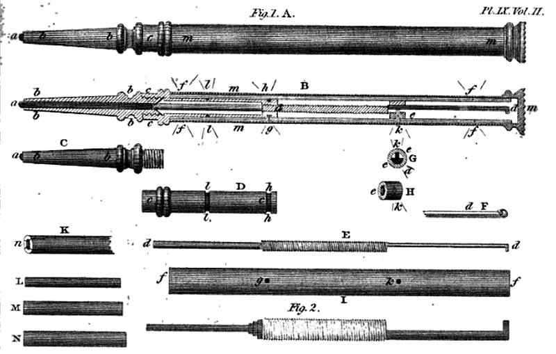
Pencil Holder - Samson Mordan - 1882
The diagram above shows the evolution of three main ideas amongst many others. The main difficulty was in finding a solution for the double linear motion system - with one mechanism moving down and the other moving up as the first exerted a downward force. Funnily, the rack and belt dilemma came back to haunt us in our quest. Remember that little episode? It was a discussion we had had right at the beginnning of the adventure, in which we explored two paths of thought: All moving parts would either be based on a toothed rack and pinion or a toothed belt system. For SAM's body, we opted for the former.
The rack and pinion however, could be a good solution for SAM's hand. Convinced by this, we embarked upon a 3D printing session to see if a small rack could be made for our design. The idea being to attach this to the side of a short t-slot aluminum extrusion. The rack could then be motorised by a small Nema 17 rotating a pinion and in turn moving the t-slot up and down.
It has to be said here that 3D printing of small detailed mechanical parts requires either a lot of patience in watching time pass by with poor results guaranteed or, most probably, just requires expert advice. Suffice to say our many attempts were a complete fail. Time being precious and our nerves on edge, we turned to another plausible solution for moving our t-slot and this time, yes you guessed it, implementing a belt and pulley system. Back to the drawing board to make the necessary changes and measurements.
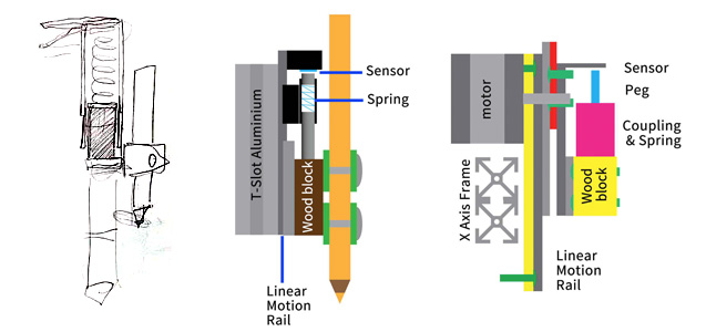
As the diagram below shows, what was nice about this solution was that we devised a means for positioning all the parts to function together in one unique and central axis. Whether this is an advantage or not, only the master of mechanics could reply. We seemed it could be a happy solution in any case.
Hand System. Frontal View - Team SPAM - 2014
Team Spam in action
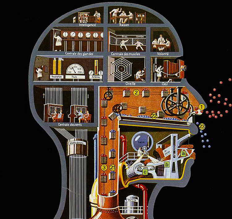
Man as an industrial palace - Fritz Kahn - 1926
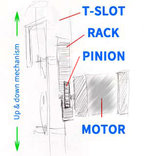
Quick Rack n' Pinion Idea. Side View - Team SPAM - 2014
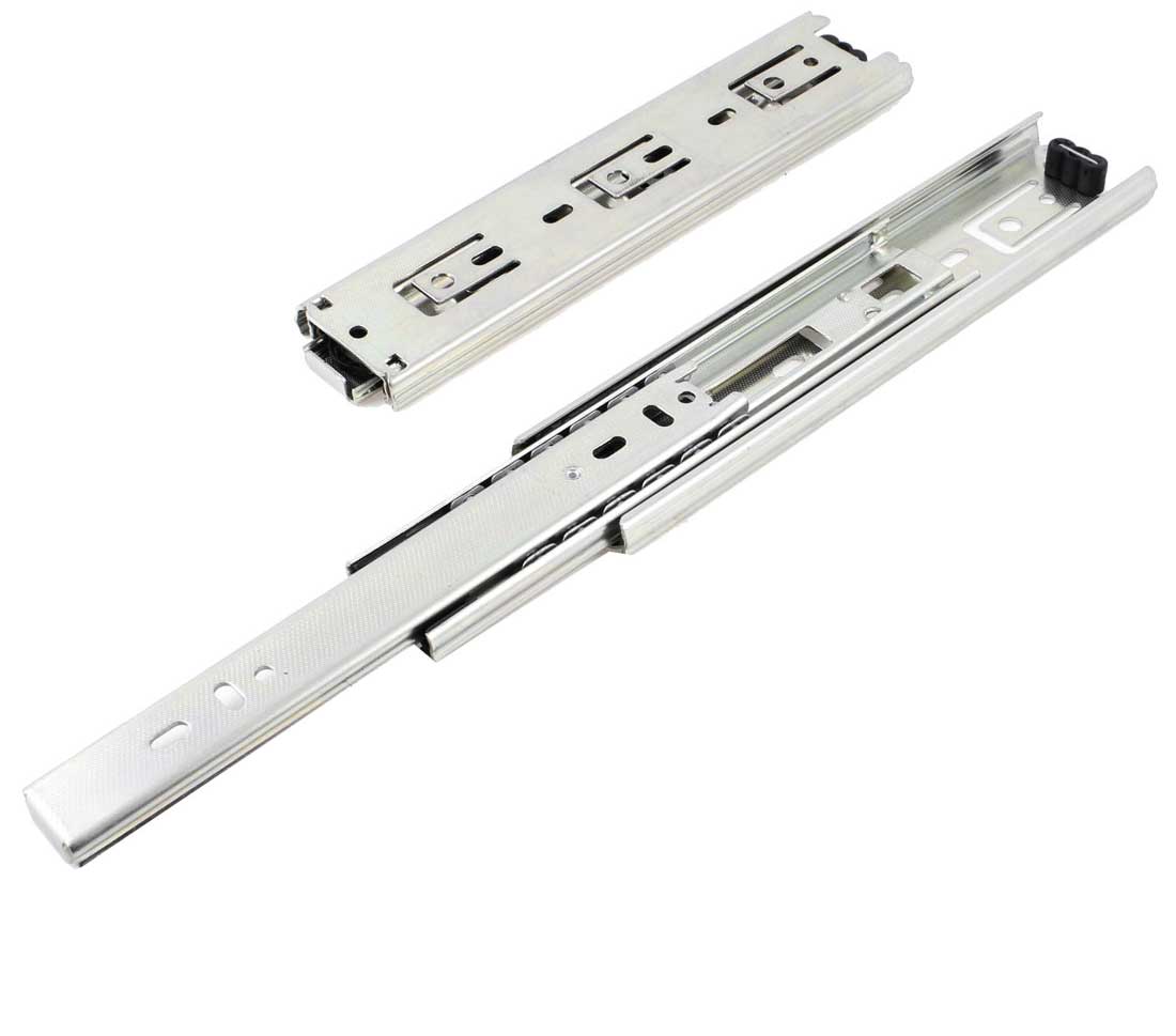
As for our neat little linear system that would attach itself to the t-slot beam, we opted for a home-made device using some spare drawer rails. 2 Aha, for those who have been diligent enough to read the whole story so far, we had in fact pondered on the good ol' household drawer linear motion system early on in our reflections. Well, that idea was put to good use here and with a piece of wood, a coupling (with the spring inside) and a cylindrical peg, we had everything in place for making SAM's hand.
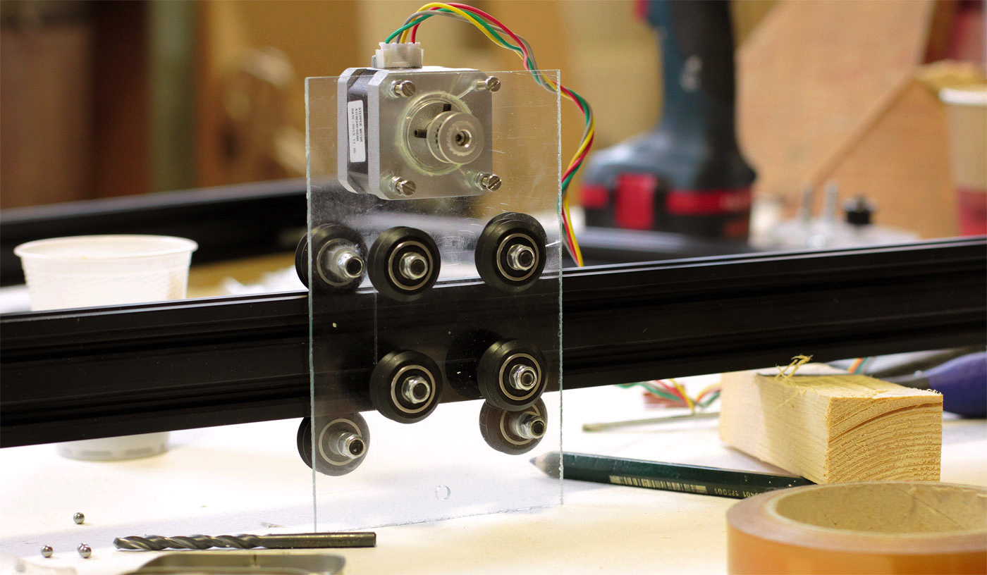
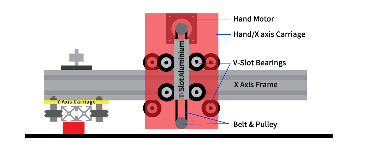
X-Axis Carriage Construction - Team SPAM - 2014
2. Household Rails
The above photo shows the x-axis carriage with the motor and linear motion v-slot bearings in place. The two photos that follow show the construction and final piece mounted. One slight detail, we hadn't fixed either a drawing tool nor the sensor in that photo. We'll reveal all on in good time once the software sessions take hold in September and we enter the final phase of SAM's creation.
Team Spam feel that this first proof of concept has a lot of potential. Admittedly, we have yet to take it for a test drive and there will no doubt be a number of modifications to perfect the whole. For now though, that's where we're at. That is, until we come back from the land of the rising sun and embark upon the programming of our little fella. What will SAM draw? Again, the quest continues and answers will only arrive once we get things operational. Stay tuned, listen to good vibes, and have fun in the sun or wherever you may find yourself this summer.
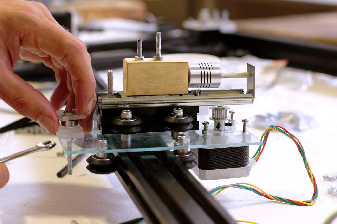
Multi-Linear Hand System - Team SPAM - 2014
What have we learned ?
Spring freaks make shop assistants nervous. Thinking outside of the box is good practice. Actually physically getting outside of the box (studio, home, corporate camp or other) is even better. On that note, holdays and rest are essential. Pack up the online world, put it in a cupboard and venture OUT...
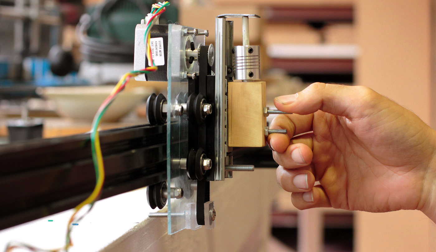
SAM's hand mounted & ready to rock - Team SPAM - 2014

