

We now have a prototype for SAM to test out some basic instructions and draw simple geometric shapes. More importantly though, this major first step has given us crucial insight into how to develop the overall design. Having tangible feedback like this is a great start for us now to take things further.
Each stage of the design process should lead us somewhere new, in terms of how we can improve on our initial ideas. In testing out new designs and making little prototypes of the various parts, we can learn what works and what doesn’t. This process of iteration invariably brings with it a whole new baggage of problems that need solutions. There within lies a danger sign ahead.
We don’t yet have a definitive design for our machine. This is partly intentional of course because SAM is a research project that has embarked on the journey of discovery. The New World is not mapped out before our eyes. The blinkerNet is perhaps our protractor, our imagination the compass. The danger therefore of such free sailing is our goal can be attained by making a plethora of choices. Unless we limit these, we are probably gonna end up sailing in a circle around the South Pole with polar bears moving in. Time therefore to make some decisive decisions and stick with them. Just before we do though, lets at least explore a few ideas.
During our research, we came across many different kinds of plotters. Each has there own unique solution for the task at hand - getting a tool to draw. We know that SAM is going to be a flat bed design, table top style and it will have a frame. This already puts aside a number of other designs that rely on pulley systems such as Jürg Lehni’s great work . Portability and scalability are not really an issue for SAM. We are looking more for a robust design that can eventually be used by other people and does not need setting up for a specific space or media. After much gleaning of the BlinkerNet, we began to see some common techniques put to use in a number of flat bed systems. Remember the ‘do we rack it or belt it’ debate. Well, this detail has turned out to be one of the crucial design issues over the past week. So, here's the lowdown so far in our quest for finding the best solution adapted to SAM's needs.
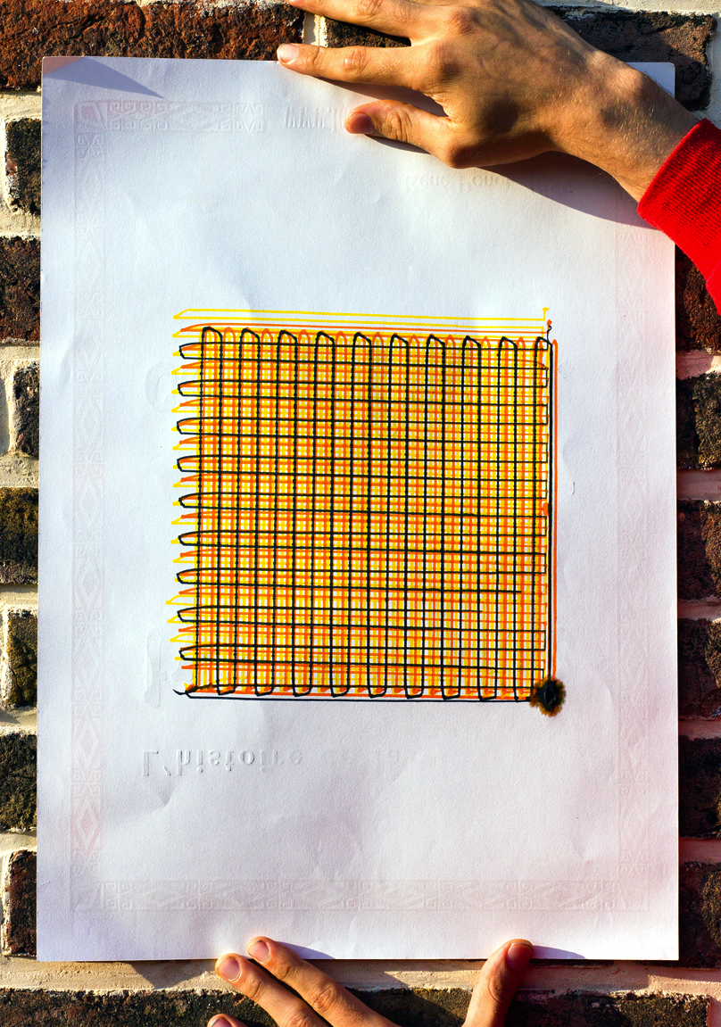
SAM draws Tartan - 06/2014
More Potty Pens
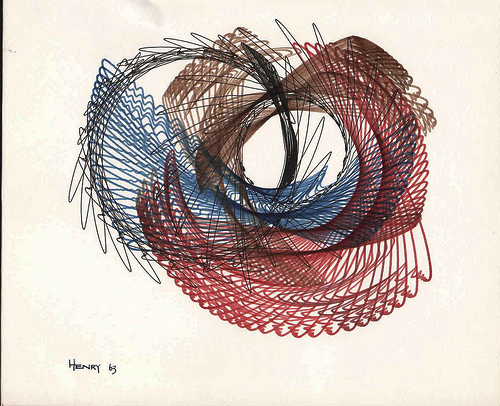
Desmond Paul Henry 1963
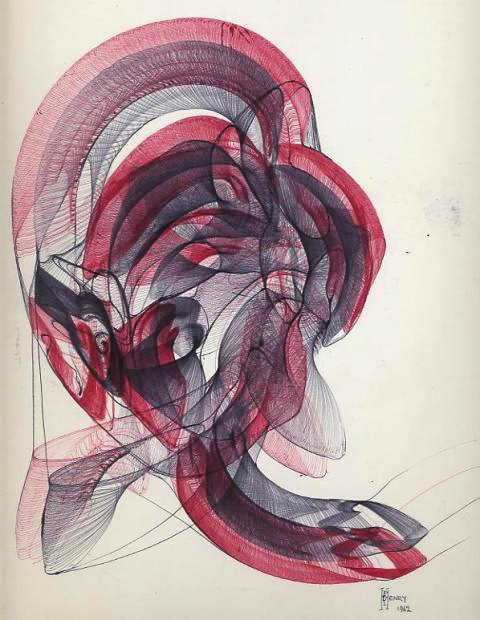
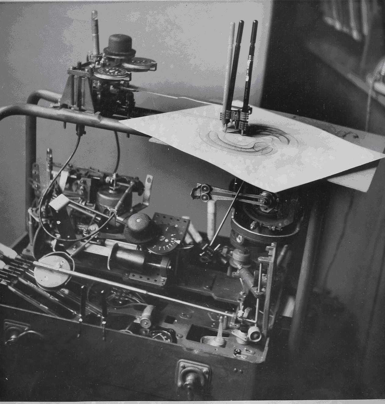
Desmond Paul Henry - 1962
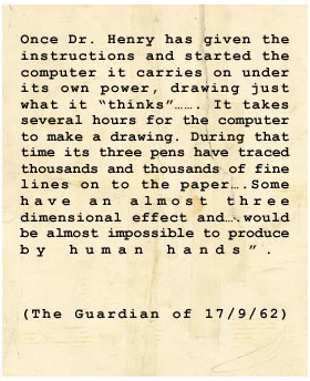
Guardian Article - 1962
Whilst SAM’s prototype took time off in Scotland meeting potential tartan producers, Team SPAM was hard at work trying to figure out the intricacies of mechanical construction making. Two words can sum up our task at hand; linear motion. Blimey, you might ask, that sounds kinda cool. We thought so too, but what does it actually mean? Well, put plainly, a linear motion system enables a rack system or anything on rails, to move loads from one position to another in a smooth and stable manner. Some basic linear motion systems can be found in ya drawers and fancy clothes closet and yes, admittedly we even took a good look at one of these as a possible solution. That is until we started searching the Ministry of Inflammation and playing videos all day long of home-made hacks to elephant gliding top notch systems. “Ah...” , we said to ourselves. “We should do that.”
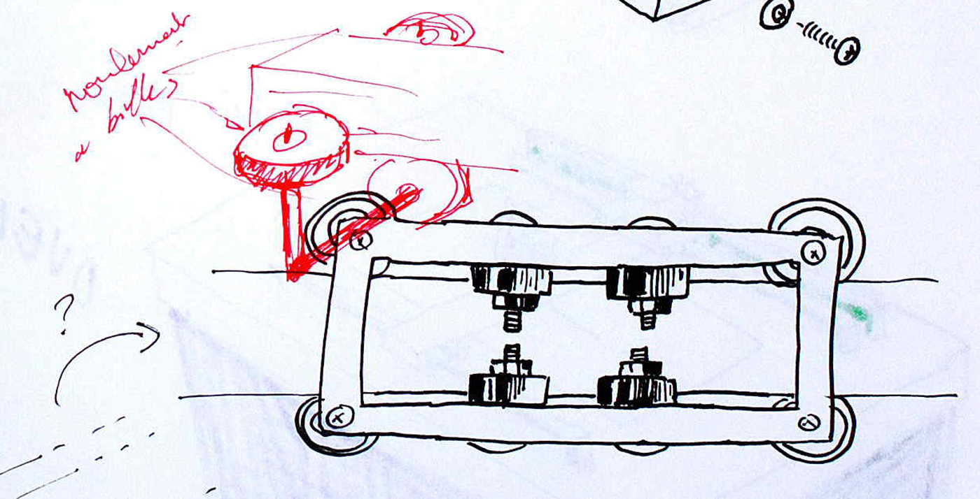
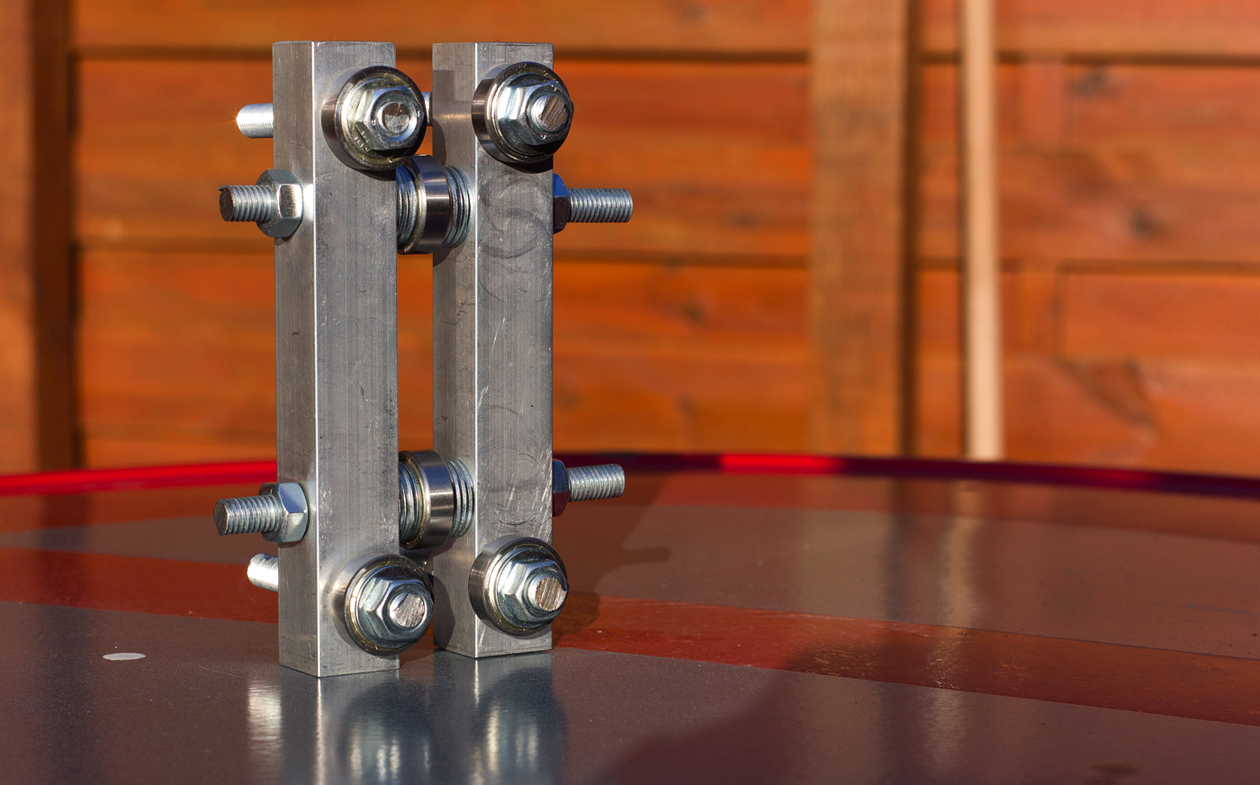
So, back to the workshop in school to try out some ideas. What we were looking for was a linear system that could be used on both the x and y axis to move three small carriages. Two carriages, on the y axis, would move up and down the main frame in perfect sync. Attached to these would be the x axis which in turn would also have a carriage for movement. The design of the x axis carriage also needed to have a system for SAM’s hand. Another detail we only have a vague idea of for the moment but we know this is where we can perhaps make a difference in terms of making SAM a little bit different from the crowd. To start with then, we opted for an extremely simple first design for the linear motion system based on a triangular rail with four bearings; two on top of the rail, two below as seen in our super pic.
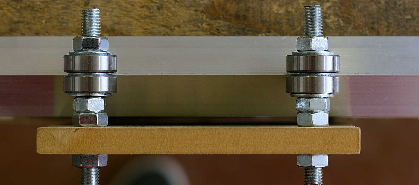
Linear Motion Prototype N°1 - Team SPAM
Linear Motion Designs
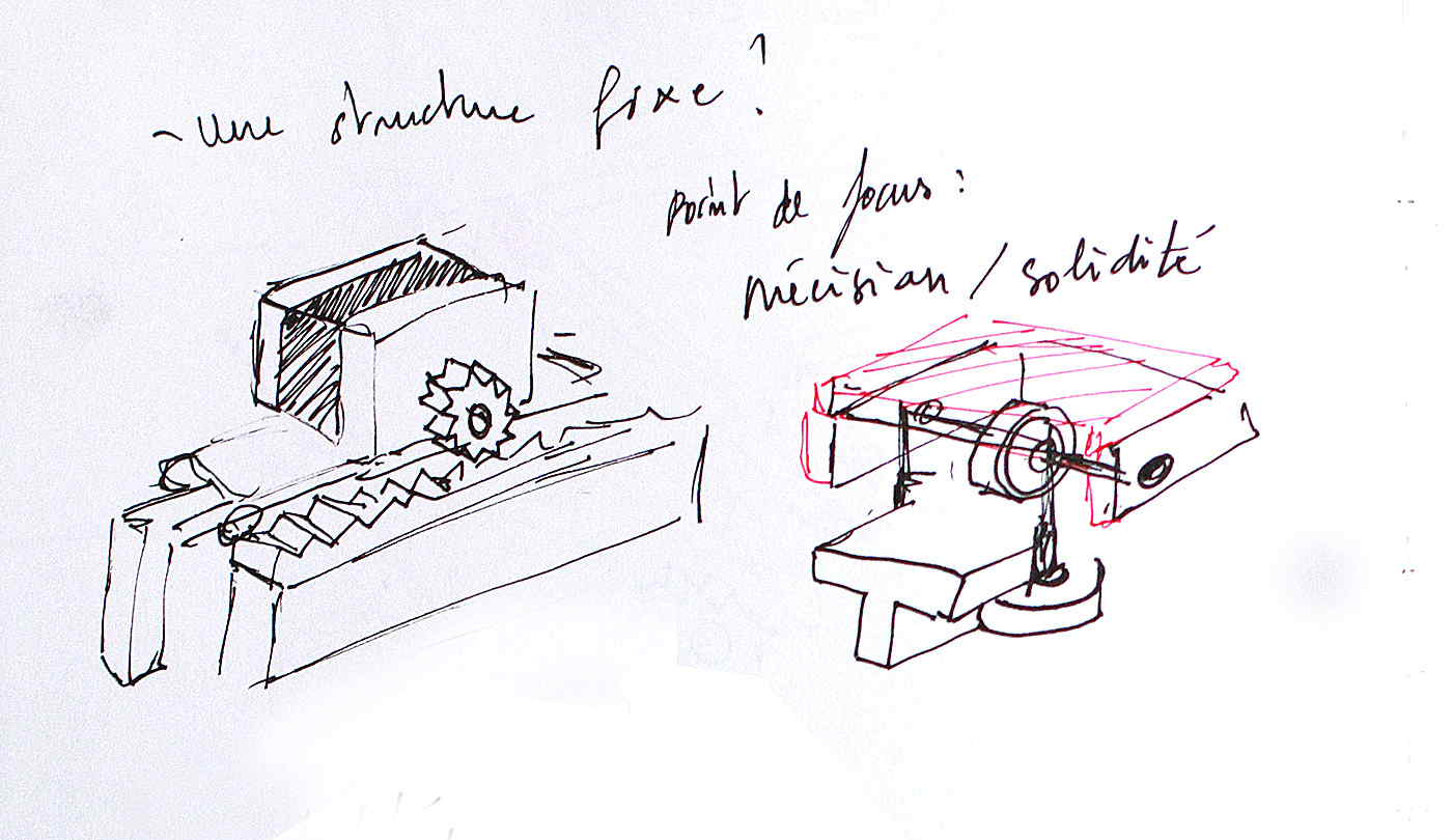
Linear Motion Designs - Team SPAM
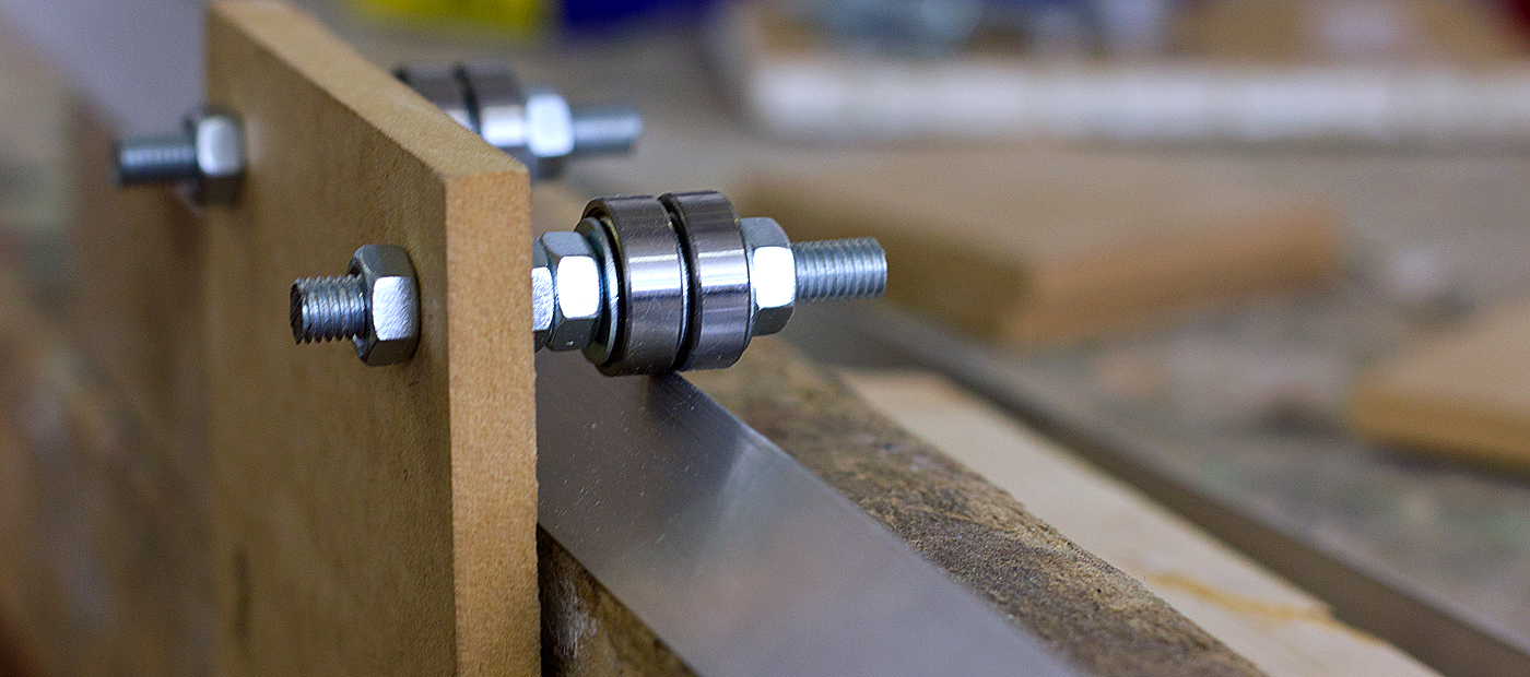
Design test fail number one. Even if this looks like it may work, the main issue here is a problem of stability and response. Testing this on a large x axis length (roughly 1m50 wide) there was a lot of play between the two carriages. Meaning, one carriage was always lagging behind the other if we exerted a force on one side. Even though this could be improved on by fixing a driving belt and two motors to each of the carriages on the y axis, therefore having equal force on both sides, we were looking for a system that would stand up to our one finger force test as best as physically possible. Back to the drawing board.
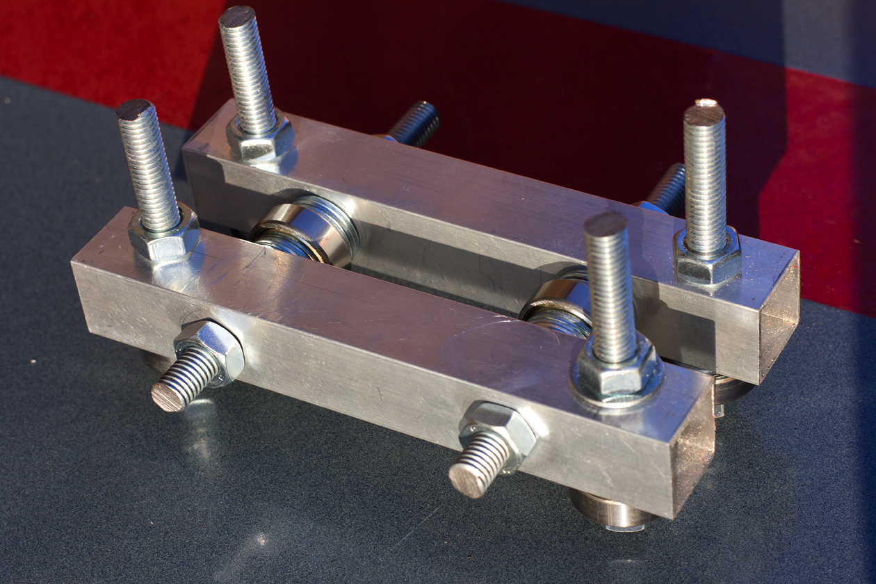
Linear Motion Prototype N°2 - Team SPAM
More Linear Systems
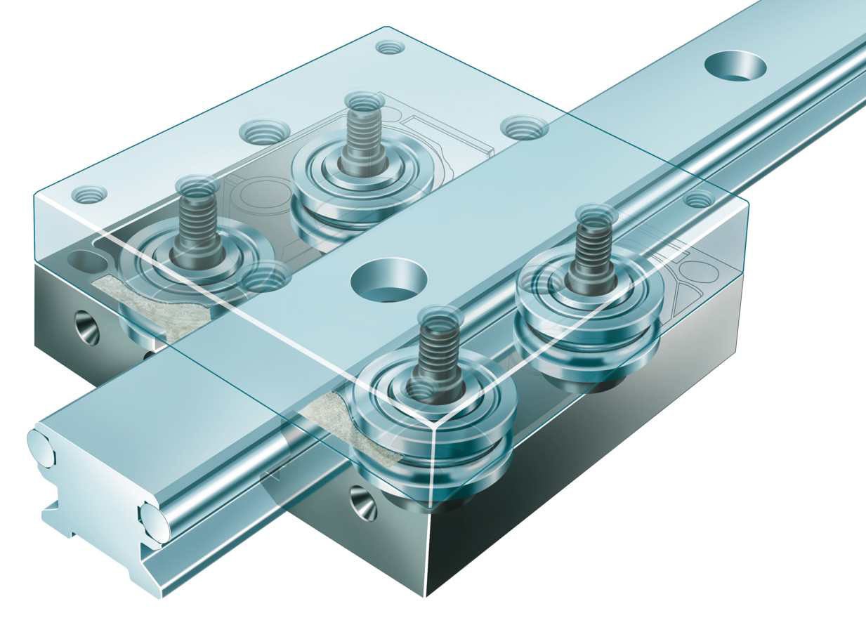
Neat System
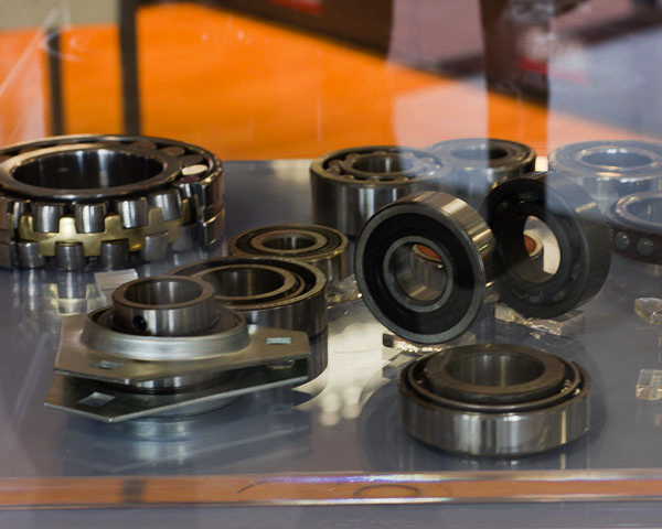
Bearing Madness
Design prototype number two was a little more convincing and brought us a tad closer to linear heaven. A few observations came about during the process. First of all, visually, our design looked, well, fuckin' brutal. This is something we design peeps are quite sensitive about. The aesthetic pleasing factor for prototype n°2 was akin to some tool knocked up by Captain Caveman. This got us thinking more about the global design of our frame and linear systems. We knew we wanted something a little more elegant and less industrial, lightweight yet sturdy. We were beginning to understand linear motion yet at the same time we were also beginning to understand our limitations as designers. Drilling holes, cutting metal, making precise measurements was not our forte. What was needed was some sort of lego kit for creative minds who couldn’t drill a straight hole. Hmmm, the bigger picture was beginning to take shape.
What have we learned ?
Making decisions means exploring the terrain, judging the risks and then sticking to your game plan with guns and cannons loaded. Linear motion is the industry standard for moving things in a smooth and robust manner. During the process of making some prototypes we realised our lack of handicraft skills were more a hinderance than a help. Lego for makers would be a more realistic solution.
Linear Motion Prototype N°2 - Team SPAM - 2014

